|
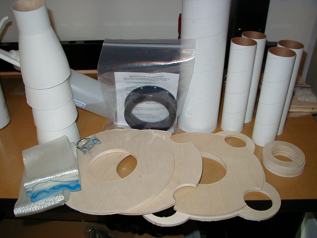
Motor mount parts.
|
|
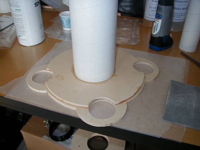
The two aft bulkheads have been epoxied to the rear of the 98mm motor mount tube.
|
|
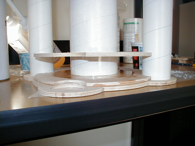
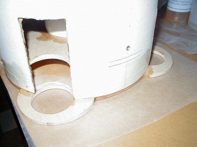
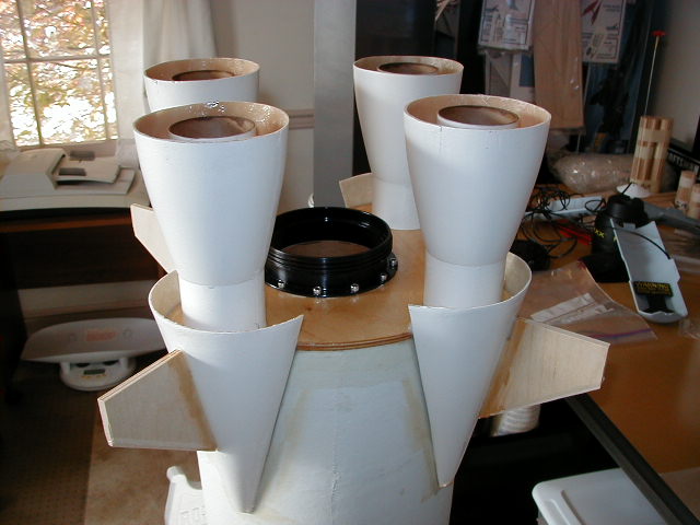
The spacer plate that holds the forward end of the outboard motor tubes
has been glued into place.
|
|
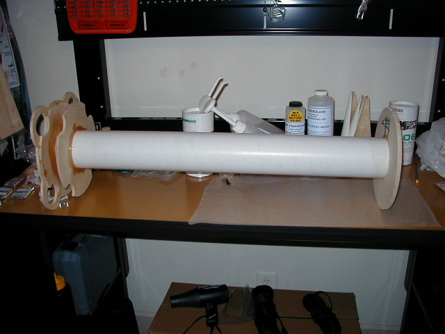
The forward motor bulkhead glued into place.
|
|
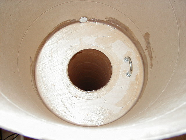
The motor mount has been glued into the main airframe.
This aft joint has been reinforced with 1" wide glass tape and epoxy.
|
|
Here is another view of the aft glue joint.
You can also see the aft rail button mount.
The button uses a 1/4-20 screw into a 1/4" blind nut.
The blind nut is reinforced with CA.
|
|
The forward motor mount space has been filleted into the main airframe.
The u-bolt is used to attach the apogee shock cord.
The masking tape on the upper part of the airframe is covering
the 1/4" blind nut used to attach the forward rail button.
|
|
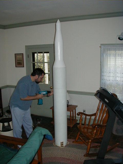
Here I'm drilling the holes for the apogee shear pins.
|
|
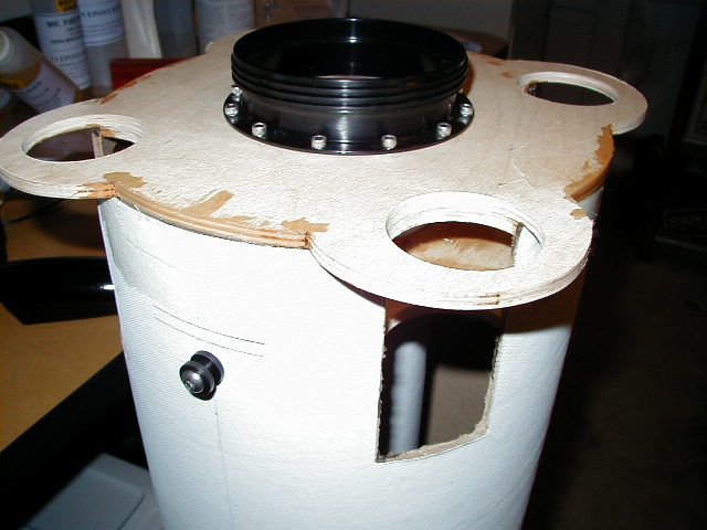
The AeroPack motor retainer has been attached to the aft bulkhead.
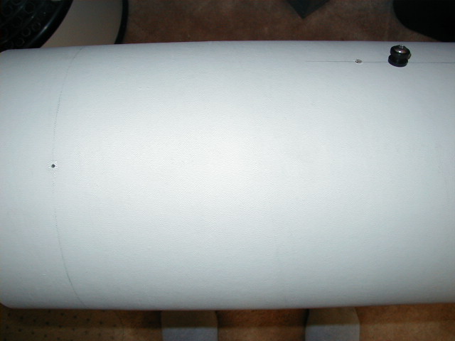
You can see the aft 1015 rail button.
I have also acquired UniStrut rail buttons.
|
|
To the left of the rail button is the 1/4" vent hole drilled to help prevent premature separation.
You can also see one of the four apogee shear pin holes.
|
|
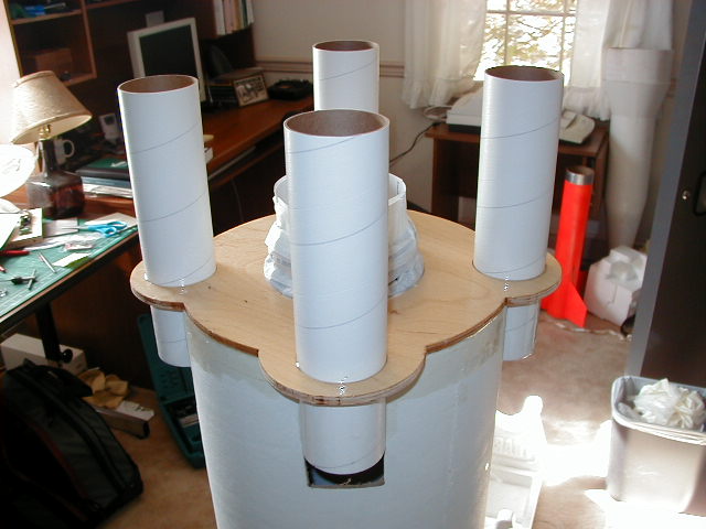
This shows the mounting of the outboard motor tubes.
|
|
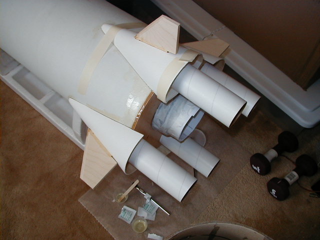
This shows the mounting of the shrouds and fins.
|
|
This shows the two 6-32 blind nuts used for motor
retention on each of the outboard motor tubes.
|
|
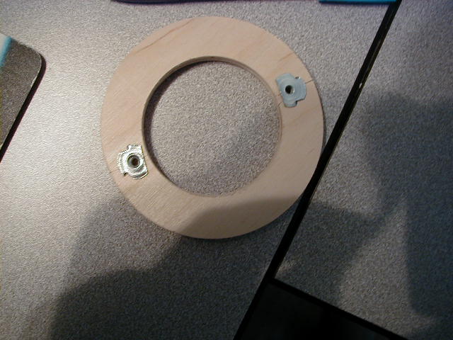
This shows the mounting of the outboard nozzles.
Each nozzle centering ring is equipped with two blind nuts
to implement motor retention.
|